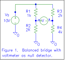
 Figure 1 shows a simple balanced Wheatstone bridge with
a voltmeter as a null detector. Let's determine the voltage indicated by
the voltmeter.
Figure 1 shows a simple balanced Wheatstone bridge with
a voltmeter as a null detector. Let's determine the voltage indicated by
the voltmeter.SAN LUIS OBISPO, Calif. Last month, we used Thevenin equivalents to analyze a simple resistive T network. One of the more common applications of Thevenin equivalents is in the analysis of an unbalanced Wheatstone Bridge.
The Wheatstone bridge is named after Sir Charles Wheatstone (1802-1875), an English physicist and inventor. The Wheatstone bridge was first described by Samuel Hunter Christie (1784-1865) in his paper Experimental Determination of the Laws of Magneto-electric Induction (1833). The circuit was brought into general use by Wheatstone in 1843. Samuel Christie was the son of James Christie, founder of the well-known auction galleries (see Dictionary of Scientific Biography; Charles Coulston Gillispie, editor). The bridge was (and is) used chiefly to measure resistance. Substituting resistances and reactances for the reference resistance in the bridge, and driving the bridge with AC, allows it to be used to measure impedance.
 Figure 1 shows a simple balanced Wheatstone bridge with
a voltmeter as a null detector. Let's determine the voltage indicated by
the voltmeter.
The voltage on the left side of the voltmeter (marked R for the red
or positive lead) with respect to ground can be determined using the
voltage divider formula as
The voltage on the right side of the voltmeter (marked B for the
black, negative, or reference lead) with respect to ground can also
be determined using the voltage divider formula as
VRB is the voltage a point R with respect to point B. Further, VRB = VR - VB. So, in this case, VRB = 0 volts. We say the bridge is balanced.
We can see that the bridge is balanced if VR =
VB. We can generalize this as
We now see that the ratio of the resistances in each "arm" of the bridge determines whether the bridge is balanced. Further, if the bridge is balanced, we can substitute an ammeter (ideally zero resistance) for the voltmeter and read zero current. If we have the same voltage at two points in a circuit and connect them together (through the ammeter), no current will flow.
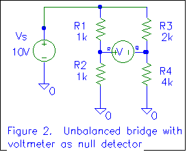 Consider the circuit of figure 2. We can see right away that the
bridge is not balanced, based on the resistance ratios (as derived
above). What will the voltmeter read?
Note that the voltage is negative. If we were to reverse the voltmeter leads, the voltage would be positive. However, as long as we specify the voltage as VRB, the voltage is negative, and polarity is important.
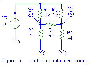 Figure 3 shows a loaded unbalanced bridge. We can still use the
resistance ratios derived above to determine that the bridge is indeed
unbalanced (current will flow through R5), but we cannot determine
how much current flows through R5 without using a technique beyond
simple voltage dividers. The "voltage divider formula" works only
in a simple series circuit, where all the current flowing in one resistor
flows in all the resistors. In figure 3, the current through R1 will equal
the current through R2 only if there is no current through R5
(Kirchoff's current law), and we have determined there is current through
R5, since the bridge is unbalanced. We'll use Thevenin equivalents to
determine the current through R5, along with all the other circuit parameters
(We'll "analyze it to death").
 Although it is quite possible (and appears standard) to bring the bridge down to a single Thevenin equivalent, I prefer to make two equivalent circuits, one for the left half of the bridge and one for the right half. This approach allows us to determine all the circuit node voltages from the equivalent circuit while the typical "single equivalent" approach only yields the "load current" (the current through R5).
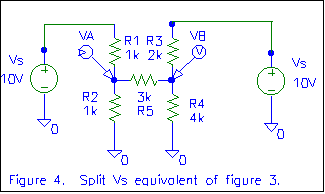 In figure 4, we've split VS into two equivalent sources.
At this point, we could determine the circuit parameters (VA
and VB would be most useful) using superposition. Give
it a try! Apply the voltage sources one at a time, substituting a short for
the voltage source that is out of circuit. Determine VA and
VB when each of the sources is present (VA due to
the left source and due to the right source), then add the
results to yield the total VA and total VB. It
should match what we come up with.
Figure 5 shows a the circuit of figure 4 with Thevenin equivalents for each "half" of the circuit. V12 is the Thevenin voltage formed by the left 10 volt source, R2, and R1. It is the voltage measured at the junction of R1 and R2 (point A) with R5 disconnected. Since this then becomes a simple voltage divider, V12 is (R2/(R1+R2))*10V, or 5 volts.
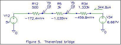 R12 is the Thevenin resistance of the left half of the circuit. This
is determined by shorting out all voltage sources and measuring the resistance
between point A and ground, with R5 removed. The shorted voltage source
results in R1 being in parallel with R2, so the Thevenin resistance is
1K//1K or 500 ohms.
Similarly, V34 is the Thevenin voltage formed by the right 10 volt source, R4, and R3. It is the voltage measured at the junction of R3 and R4 (point B) with R5 disconnected. Since this also becomes a simple voltage divider, V34 is (R4/(R3+R4))*10V, or 6.667 volts.
In figure 5, these Thevenin equivalents are substituted for the original voltage sources and R1, R2, R3, and R4. R5 is carried to the equivalent circuit. The unbalanced loaded bridge has become a simple series circuit that can be analyzed using "differential Ohm's law". The current through the resistors is (Vtail-Vtip)/R, or (6.667V-5V)/4.833K = 344.8uA. This current can then be multiplied by the resistance of each resistor to get the voltage across that resistor. Note the marked voltage polarities and the current direction. I think these are very important! With conventional current, the current flows downhill (from higher voltage to lower), so that is the way the arrow was drawn. If the arrow had been drawn the other way, we would get a negative current. A negative current going to the right is equivalent to a positive current going to the left. Further, with a positive conventional current, the voltage across a resistor will be positive on the end the current enters and negative on the end the current leaves.
We can verify our calculations by using Kirchoff's Voltage Law (the sum of the voltage rises or drops around any closed loop is zero). If we add the voltage rises, starting at the bottom of the left battery, we find we have 5V + 172.4mV + 1.035V + 459.8mV - 6.667V = 200uV, which is close to zero. The only reason it's not exactly zero volts is due to rounding errors in our calculations. Close enough!
To determine the voltage at any point in the circuit, we can start at a point where we know the voltage (with respect to ground) and "wind" our way through the circuit accumulating voltage rises and drops. For example, to determine the voltage a point A, we can start at ground on the left side of figure 5. Ground is zero volts. We "go up" 5 volts as we go through V12, since we are "coming out" the positive side of V12 as we work our way towards point A. We go up an additional 172.4 mV as we go through R12, since we are also coming out the positive side of R12. This makes VA 5.1724 volts.
We could have determined VA starting below the right voltage source. In that case, we start at zero volts below the source, go up 6.667 volts going through V34, go down 459.8mV as we go through R34 (since we are coming out the negative end), then go down an additional 1.035 volts as we go through R5. In this case, VA = 6.667V - 459.8mV - 1.035V = 5.1722 volts. The minor difference is, again, due to rounding.
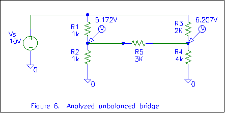 We have a couple ways of finding VB. Let's just say
it's 1.035 volts above VA or 6.207 volts. These voltages are
substituted back in the original circuit in figure 6. Once these voltages
are known, all node voltages in the circuit are known. Differential voltages
can be easily determined by subtracting
(VAB=VA-VB). Current through any component
can be determined by "differential Ohm's law". By making these calculations,
we can "analyze the circuit to death". As practice, try showing that the
sum of the currents into the node at the junction of R1, R2, and R5
is zero (Kirchoff's current law). I get 4.828mA + (-5.172mA) + 345uA = 1uA.
Pretty close!
Next time we'll look at Norton equivalents, followed by Millman's Theorem. Ten extra points to anyone who sends me biographical information on Norton or Millman.